77GHz Millimeter-Wave Radar PCB: Unlocking Performance with RO3003+FR4 Hybrid Lamination
Introduction
The rapid evolution of autonomous driving andADAS has made 77GHz millimeter-wave (mmWave) radar a cornerstone of automotive safety systems. Operating at 77GHz, these radars deliver high-resolution sensing for adaptive cruise control (ACC), automatic emergency braking (AEB), and collision warning—even in harsh weather conditions like rain, fog, or snow.
However, designing a 77GHz radar PCB poses unique challenges: extremely low signal loss, precise impedance control, and stable dielectric performance at mmWave frequencies. Standard FR4 PCBs fail here due to high dissipation factors (Df ≈ 0.02 at 77GHz) and unstable dielectric constants (Dk), leading to severe signal attenuation and inaccurate ranging.
The solution RO3003+FR4 hybrid lamination—a cost-effective stack-up that combines the high-frequency performance of Rogers RO3003 (ceramic-filled PTFE) with the mechanical strength and low cost of standard FR4. In this blog, we’ll explore why this hybrid structure dominates 77GHz radar design, its key benefits, critical design considerations (updated for an 8-layer stack-up), and real-world applications.
RO3003+FR4 Hybrid Lamination: The Best of Both Worlds
Rogers RO3003 (including the enhanced RO3003G2 variant) is a ceramic-filled PTFE laminate designed explicitly for 77GHz radar and mmWave applications. Its key properties:
-
Dk: 3.00 ± 0.04 (stable across 8–77GHz, minimal temperature drift: -35 ppm/°C).
-
Df: 0.0010 at 10GHz (ultra-low loss, 1/20th of FR4).
-
CTE: 17/16/25 ppm/°C (X/Y/Z axes) for excellent thermal stability.
-
Copper: Very Low Profile (VLP) ED copper (Ra < 0.5μm) to minimize conductor loss.
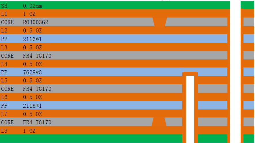
8-Layer Hybrid Stack-Up Architecture (Optimized for 77GHz Radar)
The 8-layer RO3003+FR4 hybrid structure is ideal for advanced 77GHz radar systems (e.g., 4D imaging radar, MIMO arrays) that require integrated RF, digital, power, and control circuits. It separates high-frequency and low-frequency domains while ensuring signal integrity, rigidity, and cost efficiency. The stack-up design (from top to bottom, L1 to L8) is as follows:
-
L1 (Top Layer): Rogers RO3003 (0.127mm thick) – 77GHz Antenna Elements & RF Feed Networks. This layer directly handles mmWave signals, so RO3003’s ultra-low loss and stable Dk are critical for minimizing signal attenuation and ensuring uniform antenna performance.
-
L2: Rogers RO3003 – RF Transceiver Circuits & Couplers. Extending RO3003 to the second layer keeps high-frequency signal paths short and consistent, reducing insertion loss between the antenna and transceiver.
-
L3: Standard FR4 – Solid RF Ground Plane. A continuous, unbroken ground plane directly below the RO3003 layers blocks crosstalk, provides impedance reference, and absorbs stray EM radiation.
-
L4: Standard FR4 – Power Distribution Network (PDN) & RF Bias Circuits. This layer supplies stable power to the RF transceiver, with dedicated traces to minimize noise coupling to high-frequency circuits.
-
L5: Standard FR4 – Digital Ground Plane. Isolates digital noise from RF and power circuits, preventing interference that could degrade radar performance.
-
L6: Standard FR4 – Digital Control Circuits (MCU, FPGA, ADC/DAC). Houses the radar’s processing unit and signal conversion components, leveraging FR4’s cost-effectiveness and compatibility with standard SMT components.
-
L7: Standard FR4 – IO Interfaces & Communication Bus (CAN/LIN/Ethernet). Manages data transfer between the radar and the vehicle’s main ECU, using FR4’s mechanical stability for reliable connector mounting.
-
L8 (Bottom Layer): – Secondary Ground Plane & Thermal Relief Pads. Provides additional mechanical support, enhances heat dissipation for power components, and reinforces ground integrity.
Bonding Layer Note: Use specialized high-frequency prepreg (e.g., Rogers 2929) between RO3003 layers (L1-L2) and between RO3003 and FR4 (L2-L3) to ensure strong adhesion, minimal resin flow, and no delamination during reflow soldering (260°C peak).
Real-World Applications
1. Automotive ADAS Radars
-
Long-range radar (LRR): 8-layer RO3003+FR4 PCBs power ACC and AEB systems in modern vehicles (e.g., Tesla Model Y, Audi Q7, Toyota Camry), delivering 250m detection range with ±0.05° angular accuracy.
-
4D imaging radar: The 8-layer design enables 32×64 MIMO antenna arrays (24dBi gain) for high-resolution point-cloud sensing—critical for Level 3+ autonomous driving, where precise object detection (pedestrians, cyclists, small vehicles) is essential.
2. Industrial & Smart Sensing
-
Level gauges: 77GHz radar level sensors use 8-layer hybrid PCBs for non-contact measurement in harsh industrial environments (chemical plants, oil refineries), where stability and long-range detection (up to 100m) are required.
-
Traffic monitoring: High-resolution radar sensors for speed enforcement and pedestrian detection leverage the 8-layer stack-up’s integration capabilities to fit into compact, weather-resistant enclosures.
Conclusion
For advanced 77GHz millimeter-wave radar systems, the 8-layer RO3003+FR4 hybrid lamination is the optimal solution—balancing ultra-low RF loss, high integration, cost-effectiveness, and mechanical reliability. By limiting RO3003 to the critical top two RF layers and using FR4 for the remaining layers, this stack-up enables mass production of high-performance radar PCBs for automotive ADAS, industrial sensing, and next-generation smart devices.
As autonomous driving and smart sensing continue to advance, the 8-layer RO3003+FR4 hybrid PCB will remain a cornerstone of 77GHz radar design—delivering the performance, miniaturization, and cost efficiency that safety-critical and industrial applications demand.


.jpg)